Module axi_data_width_converter
This document contains technical documentation for the axi_data_width_converter module.
This module provides small footprint blocks for AXI4 and AXI3 data width conversion.
Throughout this module, the left port is the port where the
width converter is a slave, and the right port is where the width converter
is a master.
The naming convention is analogous to how block designs typically are pictured.
![digraph my_graph {
graph [ dpi = 300 ];
rankdir="LR";
cloud [ label="Your module\nAXI master" shape=none, image="cloud_700.png"];
cloud -> axi_width_converter [label="32" dir="both"];
axi_width_converter [ shape=box label=<
<table border="0" cellborder="0" cellspacing="0" cellpadding="0">
<tr>
<td align="left">Left</td>
<td cellpadding="20">AXI data width <br /> converter</td>
<td align="right">Right</td>
</tr>
</table>>];
axi_width_converter -> ddr [label="64" dir="both"];
ddr [ label="DDR" shape=box];
}](../../_images/graphviz-570dc27569340f1884956456aa8e25411a947d5e.png)
The example block diagram above illustrates upconversion.
This is when the right port, the DDR side, is wider than the left port, the user module side.
This terminology is used for both read and write.
In the opposite case, when the left port is wider than the right port, a downconversion will occur.
![digraph my_graph {
graph [ dpi = 300 ];
rankdir="LR";
cloud [ label="Your module\nAXI master" shape=none, image="cloud_700.png"];
cloud -> axi_width_converter [label="64" dir="both"];
axi_width_converter [ shape=box label=<
<table border="0" cellborder="0" cellspacing="0" cellpadding="0">
<tr>
<td align="left">Left</td>
<td cellpadding="20">AXI data width <br /> converter</td>
<td align="right">Right</td>
</tr>
</table>>];
axi_width_converter -> ddr [label="32" dir="both"];
ddr [ label="DDR" shape=box];
}](../../_images/graphviz-c8cf6d3f8dea849c5ee3f66b4c0dad948605e78c.png)
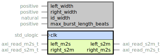
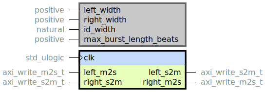
The user would typically instantiate axi_read_data_width_converter.vhd or axi_write_data_width_converter.vhd. These entities have the following generics:
left_width: Sets the data width on the left portright_width: Sets the data width on the right port.id_width: Sets the width of the ID field. Smaller values reduce resource utilization.max_burst_length_beats: Typical (and maximum) values are 256 for AXI4 and 16 for AXI3.
Specification
The module provides data width upconversion and downconversion for AXI read and write transactions.
Apart from limitations below, it is fully compliant with the AMBA AXI4 Specification.
Limitations
These AXI4 signals are not included in the interfaces, and are assumed to be constant:
Lock type:
AxLOCKMemory type:
AxCACHEProtection type:
AxPROTQuality of service:
AxQOSRegion identifier:
AxREGIONUser-defined signaling:
AxUSERandxUSERWrite ID (only used by AXI3):
WID
If
AxLOCKis asserted, the user must take care that a downconversion does not result in burst splitting.Always set
AxCACHEto be modifiable. During downconversion, the burst must be modifiable to set the new burst size. During upconversion, the implementation of this module requires that the burst is modifiable to allow data to be read as efficiently as possible.Only
INCRbursts may be used, that isAxBURSTmust be set tob01.The module does not support
AxSIZEin the general case. TheSIZEs used must be eitherleft_widthorright_width.AXI standard demands there be no combinatorial paths between input and output handshake signals (
readyandvalid). This rule is not honored in this module, since it increases logic footprint and is not necessary to reach timing.The module does not have any reset functionality. The design targets modern SRAM-based FPGAs, where initial values can be used and there is no need for reset.
axi_data_width_converter_pkg.vhd
Package with utility functions used in the rest of the module.
axi_read_data_width_converter.vhd

Wrapper module, instantiating either an upconverter or downconverter depending on the bus widths.
A throttling of different IDs is performed when width converting AXI reads.
Once a burst has been negotiated, upcoming bursts from the left side will be blocked
until the previous burst has finished, if they have different IDs.
See burst_adapter.vhd for more information.
Resource utilization
This entity has netlist builds set up with
automatic size checkers
in module_axi_data_width_converter.py.
The following table lists the resource utilization for the entity, depending on
generic configuration.
Generics |
Total LUTs |
FFs |
|---|---|---|
left_width = 32 right_width = 64 id_width = 0 max_burst_length_beats = 256 |
91 |
225 |
left_width = 64 right_width = 32 id_width = 0 max_burst_length_beats = 256 |
177 |
352 |
left_width = 32 right_width = 64 id_width = 24 max_burst_length_beats = 256 |
123 |
231 |
left_width = 64 right_width = 32 id_width = 24 max_burst_length_beats = 256 |
242 |
454 |
axi_read_data_width_downconverter.vhd

When downconverting, one input burst received on the left port may result
in two output bursts to be sent on the right port.
This module keeps track of and combines the responses in this case.
When combining different responses, this is the prioritization:
DECERRSLVERROKAYEXOKAY
For example, if one transaction resulted in OKAY and one in DECERR, the
combined response will be DECERR.
axi_read_data_width_upconverter.vhd
When upconverting, the base address and burst length on the left side might
result in transfers that are not aligned with the natural boundaries on the right
side. That means that in some scenarios we will have to read more data than we actually
want from the right side.
Any padding from the right side, at the beginning or the end, will be removed before
passing on to the left side.
The last data beat on the right port will have the last
flag set, which might be a padding word. The padding removal state machine takes care
of forwarding the last flag on the last non-padding beat.
Which beat in the burst this is depends on the burst length and base address.
axi_write_data_width_converter.vhd

Wrapper module, instantiating either an upconverter or downconverter depending on the bus widths.
Resource utilization
This entity has netlist builds set up with
automatic size checkers
in module_axi_data_width_converter.py.
The following table lists the resource utilization for the entity, depending on
generic configuration.
Generics |
Total LUTs |
FFs |
|---|---|---|
left_width = 32 right_width = 64 id_width = 0 max_burst_length_beats = 256 |
93 |
236 |
left_width = 64 right_width = 32 id_width = 0 max_burst_length_beats = 256 |
209 |
355 |
left_width = 32 right_width = 64 id_width = 24 max_burst_length_beats = 256 |
93 |
236 |
left_width = 64 right_width = 32 id_width = 24 max_burst_length_beats = 256 |
245 |
385 |
axi_write_data_width_downconverter.vhd

When downconverting, one input burst received on the left port may result in two output bursts to be sent on the right port. This module keeps track of and combines the responses in this case.
When downconverting a throttling of different IDs is performed.
Once a burst has been negotiated, upcoming bursts from the left side will be blocked
until the previous burst has finished, if they have different IDs.
See burst_adapter.vhd for more information.
axi_write_data_width_upconverter.vhd
When upconverting, the base address and burst length on the left side might
result in transfers that are not aligned with the natural boundaries on the right
side. In this case some padding must be added at the start or end of the transfers
on the right side. The padding will have it’s write strobe zero’d out, so it will
not actually be written to memory.
The W (write data) channel will be blocked until a a burst has been negotiated
(the AW channel). This is done since we must know how much padding to prepend on the
write data channel before sending left data to the right. When all data from the
left side has been written any padding needed at the end will be appended.
burst_adapter.vhd
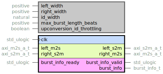
Adapts AXI bursts when changing bus data width.
The left port receives input bursts, and the right port forwards them
after manipulation. The burst_info interface supplies information for each
burst such as the amount of padding needed.
The AMBA AXI protocol specification allows transactions with different IDs to be handled in any order by a slave. Say for example that a read with ID 0 is negotiated and after that a read with ID 1 is negotiated. The data with ID 1 may very well arrive before the data with ID 0. This poses some problems for a data width converter. Below we explain the problems and how they are handled.
For transfers with the same ID, an AXI slave must send the responses in the order the transfers were negotiated.
Upconversion
For upconversion we calculate the amount of padding data needed at the beginning and end
of the outgoing burst. The padding is necessary to handle the cases where the
start or end addresses of the burst received on the left port are not aligned to the
wider right port’s address steps. When the padding is known, the output burst length
is calculated as well.
For writes, the fact that write responses may return out of order does not pose an issue,
since the write response is simply passed to the left. So outstanding bursts are
allowed to have different IDs, which can improve performance. To enable this behavior,
set upconversion_id_throttling to false.
For read upconversion, the upconverter must remember how much padding a burst used
since any padding bytes must be removed before passing on to the left.
As this information is stored in a FIFO, the read data must be returned in
the order the bursts were negotiated. This is achieved by only allowing
multiple outstanding bursts if they have the same ID. To enable this behavior,
set upconversion_id_throttling to true.
Downconversion
For downconversion we split an incoming address transaction if it would otherwise exceed
the maximum burst length on the right side.
When downconverting the ID throttling is always enabled. For writes we have to know
for each write response if it comes from a burst that was split or not. If not then the
write response shall be forwarded to the left side. If it comes from a split burst
only the last write response shall be forwarded. For reads the read responses from the
right are packed together to form a wider data word for the left bus. To handle
these cases efficiently the IDs have to be throttled so the responses are guaranteed to
arrive in order.