Module axi4_to_axi3
This document contains technical documentation for the axi4_to_axi3 module.
This module provides small footprint blocks for converting AXI4 read and write transactions to AXI3.
![digraph my_graph {
graph [ dpi = 300 splines=ortho];
rankdir="LR";
cloud [ label="AXI master" shape=none image="cloud_450.png"];
cloud -> axi4_to_axi3 [dir="both" label="AXI4"];
axi4_to_axi3 [ shape=box label=<
<table border="0" cellborder="0" cellspacing="0" cellpadding="0" height="100px">
<tr>
<td height="100px" align="left">left<br />port</td>
<td height="100px" cellpadding="40">AXI4 to AXI3<br />read/write</td>
<td height="100px" align="right">right<br />port</td>
</tr>
</table>>];
axi4_to_axi3 -> ddr [dir="both" label="AXI3"];
ddr [ label="DDR" shape=box];
}](../../_images/graphviz-aac2eade372fb390739eef5a4a393b3a7caf4670.png)
The user would typically instantiate axi4_to_axi3_read or axi4_to_axi3_write. These entities have the following generics:
address_width_bits: The width ofARADDRandAWADDRfor both AXI ports. Increasing this will increase the resource utilization.id_width_bits: The width ofARID,RID,AWIDandBIDfor both AXI ports, and additionallyWIDfor therightport. Increasing this will increase the resource utilization.data_width_bits: The width ofRDATAandWDATAfor both AXI ports.
Specification
The module provides conversion of AXI4 read and write transactions to AXI3.
Apart from the limitations below, it is fully compliant with the AMBA AXI4 and AXI3 Specification.
Achieves 100% utilization of
R,WandBchannels. No cycles wasted when converting. This is assuming no ID throttling is performed.For
ARandAWa transaction can be performed on theleftside every third cycle, and on therightside every second or third cycle depending on use case. The worst case is formed whenlefttransactions are of length 16 beats or less. In this case, an address transaction on therightside can be performed every third cycle. In other cases, when burst splitting is performed, address transactions on therightside are performed every second cycle.
Limitations
These AXI signals are not included in the interfaces, and are assumed to be constant:
Lock type:
AxLOCKMemory type:
AxCACHEProtection type:
AxPROT
Additionally AXI4 adds some signals that are not present in AXI3:
Quality of service:
AxQOSRegion identifier:
AxREGIONUser-defined signaling:
AxUSERandxUSER
These are assumed to be unused on the
leftAXI4 side and will not in any way be propagate to therightAXI3 side.AXI standard demands there be no combinatorial paths between input and output handshake signals (
readyandvalid). This rule is not honored in this module, since it increases logic footprint and is not necessary to reach timing.The module does not have any reset functionality. The design targets modern SRAM-based FPGAs, where initial values can be used and there is no need for reset.
ID throttling
This module implements throttling based on ID which is needed in some cases. Note that according to the standard an AXI slave can send read/write responses in arbitrary order if they have different ID. Whereas if they have the same ID the responses must be sent in the order the address transactions arrived.
When aggregating right side B transaction to one left side transaction,
or combining many R bursts to one burst on the left side,
we are highly dependent on responses arriving in the order that we sent the address transactions.
This means that we must stall the address channel until all responses are received, if the incoming
ID is different that the one we have outstanding (if any).
axi4_to_axi3_read.vhd
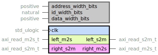
Top level for AXI4-to-AXI3 conversion of read transactions.
The difference between the read protocol for AXI4 and AXI3 is simply:
For AXI3 the burst length is limited by 16 beats, whereas for AXI4 it is limited by 256 beats.
The RRESP field in the read response channel is valid on a per-beat basis, meaning that e.g.
for some words of a burst it can be OKAY while for others it can be SLVERR.
This means that no response aggregation must be performed, despite the bursts being split.
The RRESP for the right side is simply propagated to the left side along with
the data.
This entity performs burst splitting of left transactions.
That means splitting of the burst length and incrementing the base address.
It also make sure that RLAST is only propagated to the left side for the last
splitted burst.
These features are implemented in a way that is very similar to what an AXI master
job_partitioner and axi_read_master_core would do.
Indeed when reading the code a lot of similarities can be seen.
The difference is that this code is greatly simplified since input “jobs” are guaranteed to be
compliant with the AXI standard.
Those requirements result in an implementation that is way smaller than an instantiation of
job_partitioner and axi_read_master_core.
This entity supports full throughput.
Meaning that new AR transactions can be queued up to the right side before all previous
R transactions have finished.
There is no stalling of the R channel.
There is a two cycle overhead on the AR channel for each left-side AR transaction.
If there is burst splitting performed there will be one cycle of overhead per additional burst
as well.
There is a FIFO between the state machine that performs AR transactions and the control logic
for the R channel.
This FIFO propagates the burst information that is needed to adapt the response.
Having this FIFO in place enables full throughput, since the AR state machine can move
on to the next address transaction without having to wait on the read channel.
Resource utilization
This entity has netlist builds set up with
automatic size checkers
in module_axi4_to_axi3.py.
The following table lists the resource utilization for the entity, depending on
generic configuration.
Generics |
Total LUTs |
FFs |
|---|---|---|
address_width_bits = 28 id_width_bits = 0 data_width_bits = 32 |
69 |
65 |
address_width_bits = 32 id_width_bits = 8 data_width_bits = 128 |
73 |
77 |
axi4_to_axi3_write.vhd
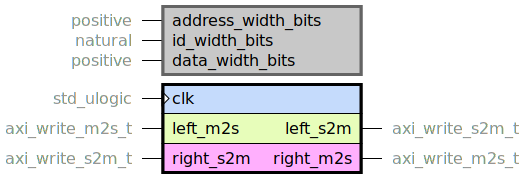
Top level for AXI4-to-AXI3 conversion of write transactions.
The difference between the write protocol for AXI4 and AXI3 is:
For AXI3 the burst length is limited by 16 beats, whereas for AXI4 it is limited by 256 beats.
For AXI3 the write channel has an ID field which is not present in AXI4.
The write response (B) sent to the left side shall be sent only once the write response
on the right side has been received for all splitted bursts. The BRESP field that is
propagated to the left is an aggregate of all BRESP from the right responses
that are part of the splitted burst.
This entity performs burst splitting of left transactions.
That means splitting of the burst length and incrementing the base address.
It also makes sure that BVALID is only sent to the left side for the last
splitted burst response.
These features are implemented in a way that is very similar to what an AXI master
job_partitioner and axi_write_master_core would do.
Indeed when reading the code a lot of similarities can be seen.
The difference is that this code is greatly simplified since input “jobs” are guaranteed to be
compliant with the AXI standard.
Those requirements result in an implementation that is way smaller than an instantiation of
job_partitioner and axi_write_master_core.
This entity supports full throughput.
Meaning that new AW transactions can be queued up to the right side before all previous
W and B transactions have finished.
There is no stalling of the W channel.
Further W transactions can be performed before the previous B transaction has occurred.
There is a two cycle overhead on the AW for each left-side AW transaction.
If there is burst splitting performed there will be one cycle of overhead per additional burst
as well.
There is a FIFO between the state machine that performs AW transactions and the control logic
for the W channel as well as the B channel.
The FIFOs propagate the burst information that is needed to adapt the write beats and
write response.
Having these FIFOs in place enables full throughput, since the AW state machine can move
on to the next address transaction without having to wait on the write or write
response channel.
In the same manner, the control logic for the W channel has no dependency on the B
channel and can move on the the next burst straight away.
Resource utilization
This entity has netlist builds set up with
automatic size checkers
in module_axi4_to_axi3.py.
The following table lists the resource utilization for the entity, depending on
generic configuration.
Generics |
Total LUTs |
FFs |
|---|---|---|
address_width_bits = 28 id_width_bits = 0 data_width_bits = 32 |
106 |
87 |
address_width_bits = 32 id_width_bits = 8 data_width_bits = 128 |
110 |
115 |