Module off_chip_fifo
This document contains technical documentation for the off_chip_fifo module.
This module provides a First In First Out (FIFO) mechanism where the data is buffered in DDR memory via AXI. It provides a simple interface, like a traditional FIFO, but can have a much greater depth (i.e. hold more data) than a FIFO that is limited by on-chip Block RAM.
In FPGA design, a FIFO is a very common component that is used to implement data flow control. It achieves a situation where data can be written at a certain rate, or in a certain pattern, but read out independently at a completely different rate or pattern. On-chip FIFOs are often implemented using Block RAM (for a depth in the 1000’s) or LUTRAM (for a depth in the 10’s). If the data read and write patterns demand a greater data buffer than that, an off-chip DDR memory can be used to buffer data, utilizing an AXI FIFO module like this.
Block diagram
Below is a simple block diagram of the module.
![digraph my_graph {
graph [ dpi = 300 ];
rankdir="LR";
input_data [ label="input" shape=none ];
w_fifo [ label="" shape=none image="fifo.png"];
ring_buffer_manager [ label="ring_buffer_manager" shape=box];
input_state_machine [ label="" shape=none image="cloud_450.png"];
job_partitioner [ label="job_partitioner" shape=box];
axi_write_master_core [ label="axi_write_master_core" shape=box];
base_addresses [ label="buffer_start_address\nbuffer_last_address" shape=none ];
input_data -> w_fifo:w;
input_data -> input_state_machine:w;
base_addresses:e -> ring_buffer_manager;
input_state_machine -> ring_buffer_manager:w [ label="request" dir="both" ];
input_state_machine -> job_partitioner;
job_partitioner:e -> axi_write_master_core:w
w_fifo -> axi_write_master_core
axi_write_master_core:e -> axi [ label="AW, W" ]
axi [ label="AXI\nDDR" shape=box height=2.5 ];
read_job_fifo [ label="" shape=none image="fifo.png"];
output_state_machine [ label="" shape=none image="cloud_450.png"];
axi_read_master_core [ label="axi_read_master_core" shape=box];
output_data [ label="output" shape=none ];
axi -> output_data [ label="R" ];
axi -> output_state_machine [ label="B" ]
job_partitioner:e -> read_job_fifo:w;
read_job_fifo:e -> output_state_machine;
output_state_machine -> axi_read_master_core;
axi -> axi_read_master_core [ label="AR" dir="back" ];
ring_buffer_manager:e -> output_state_machine:s [ label="release" dir="back" ];
{
rank=same;axi;output_state_machine;
}
}](../../_images/graphviz-8f13bd654f3db239f52541067138955f36682312.png)
Note that the job_partitioner, which splits bursts into smaller chunks, is only needed if
Otherwise, no burst splitting is necessary, since the whole packet length can fit in one burst.
Performance
This module uses AXI read and write ports of the same width as the native data port.
The module can not sustain full throughput on the input interface over time.
For each AXI burst there is a two clock cycle stall on the data flow.
This means that, if continuously fed with data, the data FIFO will build up, which will eventually cause input_ready to be lowered.
With this in mind, the depth of the data FIFO must be chosen carefully.
It must be able to hold a packet of maximum length, but could also have spare space to handle a build up of data.
Spare space should be dimensioned based on the behavior of input stream, so that back-to-back packets can be handled as necessary.
On the output side there is no limitation in throughput.
Handshake data interface
This module uses handshaking for data qualification on the input and output interfaces.
Using AXI4-Stream-like handshake interfaces (ready and valid to qualify data transactions)
is very common in FPGA designs.
It enables a backpressure situation where the slave, i.e. the receiver of data, can indicate when it
is ready to receive the data.
Below are some rules governing how these handshake signals interact. They are adapted from the AMBA 4 AXI4-Stream Protocol Specification, ARM IHI 0051A (ID030610).
A transactions occurs on the positive edge of the clock when both
readyandvalidare high. The graph below shows some typical transactions.
The
readysignal may fall without a transaction having occurred:
The
validsignal may NOT fall without a transaction having occurred:
Once
validis asserted, the associated data may NOT be changed unless a transaction has occurred.
This applies to any auxillary signals associated with the bus as well, e.g. a
lastindicator.Note also that this restriction on data not changing only applies when
validis asserted. When it is not, the data may be changed freely.In order to avoid deadlock situations, the master may NOT wait for the slave to assert
readybefore assertingvalid. The slave however may wait forvalidbefore assertingready.
off_chip_fifo.vhd
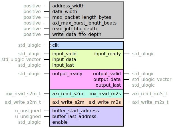
This entity provides a FIFO structure where data is buffered in memory via AXI.
Set buffer addresses
See off_chip_ring_buffer_manager.vhd for information on how to correctly set the buffer base addresses.
Limitations
In order to keep complexity and resource utilization down, it uses a simple AXI mechanism that implies a limitation:
Warning
The buffer_start_address must be a multiple of
\[\frac{\text{data_width}}{8}.\]
However, in order to achieve the best memory performance, it is beneficial if
buffer_start_address is multiple of 4096. This will minimize the rate of
burst splitting.
AXI behavior
This entity does not contain a data FIFO on the output side.
It is up to the user what type of buffering they need (synchronous or asynchronous, on the
output side or on the R side, …).
With that in mind, the AR transactions that this entity performs are not necessarily well
behaved in an AXI sense:
It is possible that more R transactions are queued up than what the R slave can receive.
If this is the case, it would result in degradation of memory performance.
Given this risk, it is recommended to have an R FIFO in conjunction with
an axi_read_throttle instance in your AXI subsystem.
Resource utilization
This entity has netlist builds set up with
automatic size checkers
in module_off_chip_fifo.py.
The following table lists the resource utilization for the entity, depending on
generic configuration.
Generics |
Total LUTs |
FFs |
RAMB18 |
RAMB36 |
|---|---|---|---|---|
address_width = 28 data_width = 64 max_packet_length_bytes = 1526 axi_max_burst_length_beats = 256 read_job_fifo_depth = 8 write_data_fifo_depth = 1024 |
378 |
345 |
0 |
2 |
off_chip_fifo_pkg.vhd
Package with utility functions used in the rest of the module.
off_chip_ring_buffer_manager.vhd
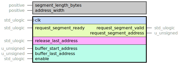
This entity provides a simplified/specialized application for handling segments in a ring buffer,
without a buffer_head_address or buffer_last_address.
These two must be handled by mechanisms outside of this entity.
It instantiates the general ring_buffer_manager, but with a local handling of
buffer_last_address.
Warning
As soon as enable is asserted, this entity will start serving addresses on
the request_segment interface. To avoid faulty operation, the user must make sure that:
The buffer addresses must be correctly set before starting any operation.
Once set, the buffer addresses must not be changed.
Also, there is no internal error checking for how many addresses are outstanding:
Warning
Do not use the release interface to release more addresses than you have request ed.
Resource utilization
This entity has netlist builds set up with
automatic size checkers
in module_off_chip_fifo.py.
The following table lists the resource utilization for the entity, depending on
generic configuration.
Generics |
Total LUTs |
FFs |
DSP Blocks |
|---|---|---|---|
address_width = 28 segment_length_bytes = 2048 |
146 |
89 |
0 |